
Product Description
CHINAMFG and CHINAMFG Type telescopic cylinder for dump truck and trailer body
1. Company Information
Found 1995,w are 1 of the biggest hydraulic cylinder manufacturer in China, specialized in design, R & D and manufacturing of hydraulic machinery products etc, with its annual production capaciy of 2 square meters.There are 700 sets of mnufacturing equipment .
Product Description
2. hydraulic telescopic cylinder for dump truck drawing and parameter
Hyva FE type
| ITEM | MODLE NO. | # of Stages | Largest Moving Stage Diameter(mm) | stroke(mm) | mounting distance(mm) |
| 1 | WTHY FE-3-110-3205 | 3 | 110 | 3205 | 1449 |
| 2 | WTHY FE-3-110-3460 | 3 | 110 | 3460 | 1609 |
| 3 | WTHY FE-3-129-3460 | 3 | 129 | 3460 | 1449 |
| 4 | WTHY FE-3-129-3880 | 3 | 129 | 3880 | 1609 |
| 5 | WTHY FE-3-149-2900 | 3 | 149 | 2900 | 1320 |
| 6 | WTHY FE-3-149-3200 | 3 | 149 | 3200 | 1420 |
| 7 | WTHY FE-3-149-3500 | 3 | 149 | 3500 | 1520 |
| 8 | WTHY FE-3-149-3880 | 3 | 149 | 3880 | 1644 |
| 9 | WTHY FE-4-149-4280 | 4 | 149 | 4280 | 1450 |
| 10 | WTHY FE-4-149-4940 | 4 | 149 | 4940 | 1529 |
| 11 | WTHY FE-4-149-4620 | 4 | 149 | 4620 | 1484 |
| 12 | WTHY FE-4-169-4280 | 4 | 169 | 4280 | 1394 |
| 13 | WTHY FE-4-169-4450 | 4 | 169 | 4450 | 1437 |
| 14 | WTHY FE-4-169-4620 | 4 | 169 | 4620 | 1479 |
| 15 | WTHY FE-4-169-4940 | 4 | 169 | 4940 | 1529 |
| 16 | WTHY FE-4-169-5000 | 4 | 169 | 5000 | 1574 |
| 17 | WTHY FE-4-169-5180 | 4 | 169 | 5180 | 1604 |
| 18 | WTHY FE-5-169-5355 | 5 | 169 | 5355 | 1394 |
| 19 | WTHY FE-5-169-5780 | 5 | 169 | 5780 | 1559 |
| 20 | WTHY FE-5-169-6180 | 5 | 169 | 6180 | 1527 |
| 21 | WTHY FE-5-169-6480 | 5 | 169 | 6480 | 1604 |
| 22 | WTHY FE-5-169-6830 | 5 | 169 | 6830 | 1674 |
| 23 | WTHY FE-5-169-7130 | 5 | 169 | 7130 | 1769 |
| 24 | WTHY FE-5-191-6180 | 5 | 191 | 6180 | 1527 |
| 25 | WTHY FE-5-191-9030 | 5 | 191 | 9030 | 2177 |
| 26 | WTHY FE-6-191-7420 | 6 | 191 | 7420 | 1677 |
| 27 | WTHY FE-5-214-6830 | 5 | 214 | 6830 | 1662 |
| 28 | WTHY FE-5-214-7130 | 5 | 214 | 7130 | 1722 |
Parker and Custom hoists kind
| ITEM | MODEL NO. | Largest Moving Stage Diameter | # of Stages | STROKE | CLOSED LENGTH | OPEN LENGTH |
| 1 | WTPK 3TG F5*72 | 5″ | 3 | 72″(1829mm) | 37.19″ (945mm) | 109.19″ (2773mm) |
| 2 | WTPK 3TG F5*84 | 5” | 3 | 84″ (2134mm) | 41.19″ (1046mm) | 125.19″ (3180mm) |
| 3 | WTPK 3TG F5*107 | 5″ | 3 | 107.56″ (2732mm) | 48.38″ (1229mm) | 155.94″ (3961mm) |
| 4 | WTPK 3TG F5*126 | 5″ | 3 | 126.63″ (3216mm) | 54.56″ (1386mm) | 181.19″ (4602mm) |
| 5 | WTPK 3TG F6*86 | 6″ | 3 | 86.75″ (2203mm) | 40.88″ (1038mm) | 127.63″ (3241mm) |
| 6 | WTPK 3TG F6*104 | 6″ | 3 | 103.94″ (2640mm) | 47″ (1194mm) | 150.94″ (3834mm) |
| 7 | WTPK 3TG F6*107 | 6″ | 3 | 107.56″ (2732mm) | 48.38″ (1289mm) | 155.94″ (3961mm) |
| 8 | WTPK 3TG F6*111 | 6” | 3 | 111″ (2819mm) | 49.94″ (1268mm) | 160.94″ (4087mm) |
| 9 | WTPK 3TG F6*120 | 6” | 3 | 120” (3048mm) | 53.5″ (1359mm) | 173.5″ (4407mm) |
| 10 | WTPK 3TG F6*123 | 6” | 3 | 123″ (3124mm) | 54.94″ (1395mm) | 177.94″ (4519mm) |
| 11 | WTPK 3TG F6*126 | 6” | 3 | 126.31″(3208mm) | 54.56″ (1386mm) | 180.87″ (4594mm) |
| 12 | WTPK 3TG F6*140 | 6” | 3 | 140.25″ (3562mm) | 59.81″ (1519mm) | 200.06″ (5081mm) |
| 13 | WTPK 4TG F6*135 | 6” | 4 | 135″ (3429mm) | 47.19″ (1199mm) | 182.19″ (4628mm) |
| 14 | WTPK 4TG F6*156 | 6” | 4 | 156″ (3962mm) | 53.62″ (1362mm) | 209.62″ (5324mm) |
| 15 | WTPK 3TG F7*110 | 7″ | 3 | 110.63″ (2810mm) | 50.06″ (1271mm) | 160.69″ (4081mm) |
| 16 | WTPK 3TG F7*120 | 7″ | 3 | 120″ (3048mm) | 53.12″ (1349mm) | 173.12″ (4397mm) |
| 17 | WTPK 3TG F7*124 | 7″ | 3 | 124.88″ (3172mm) | 54.81″ (1392mm) | 179.69″ (4564mm) |
| 18 | WTPK 3TG F7*129 | 7″ | 3 | 129″ (3277mm) | 56.5″ (1435mm) | 185.5″ (4712mm) |
| 19 | WTPK 3TG F7*140 | 7″ | 3 | 140.44″ (3567mm) | 60″ (1524mm) | 200.44″ (5091mm) |
| 20 | WTPK 3TG F7*150 | 7″ | 3 | 150″ (3810mm) | 63.50″ (1613mm) | 213.50″ (5423mm) |
| 21 | WTPK 4TG F7*120 | 7″ | 4 | 120″ (3048mm) | 44.12″ (1120mm) | 164.12″ (4168mm) |
| 22 | WTPK 4TG F7*135 | 7″ | 4 | 135″ (3429mm) | 48.43″ (1230mm) | 183.44″ (4659mm) |
| 23 | WTPK 4TG F7*140 | 7″ | 4 | 140″ (3556mm) | 49.75″ (1263mm) | 189.75″ (4819mm) |
| 24 | WTPK 4TG F7*156 | 7″ | 4 | 156″ (3962mm) | 53.75″ (1365mm) | 209.75″ (5327mm) |
| 25 | WTPK 4TG F7*161 | 7″ | 4 | 161.75″ (4108mm) | 55.31″ (1405) | 217.06″ (5513mm) |
| 26 | WTPK 4TG F7*167 | 7″ | 4 | 167″ (4242mm) | 56.38″ (1432mm) | 223.38″ (5674mm) |
| 27 | WTPK 4TG F7*180 | 7″ | 4 | 180″ (4572mm) | 61.12″ (1552mm) | 241.12″ (6124mm) |
| 28 | WTPK 4TG F8*148 | 8″ | 4 | 147.75″ (3753mm) | 51.50″ (1308mm) | 199.25″ (5061mm) |
| 29 | WTPK 4TG F8*156 | 8″ | 4 | 156″ (3962mm) | 53.75″ (1365mm) | 209.75″ (5327mm) |
| 30 | WTPK 4TG F8*161 | 8″ | 4 | 160″ (4064mm) | 55.75″ (1416mm) | 215.75″ (5480mm) |
| 31 | WTPK 4TG F8*170 | 8″ | 4 | 170″ (4318mm) | 57.25″ (1454mm) | 227.25″ (5481mm) |
| 32 | WTPK 4TG F8*180 | 8″ | 4 | 180″ (4572mm) | 59.75″ (1518mm) | 239.75″ (6090mm) |
| 33 | WTPK 5TG F8*170 | 8″ | 5 | 170″ (4318mm) | 49.88″ (1267mm) | 219.88″ (5585mm) |
| 34 | WTPK 5TG F8*190 | 8″ | 5 | 189″ (4800mm) | 54.62″ (1387mm) | 243.62″ (6188mm) |
| 35 | WTPK 5TG F8*220 | 8″ | 5 | 220″ (5588mm) | 60″ (1524mm) | 280″ (7112mm) |
| 36 | WTPK 5TG F8*235 | 8″ | 5 | 234″ (5944mm) | 64.62″ (1641mm) | 298.62″ (7585mm) |
| 37 | WTPK 5TG F8*250 | 8″ | 5 | 249″ (6325mm) | 68.62″ (1743mm) | 317.62″ (8068mm) |
| 38 | WTPK 5TG F8*265 | 8″ | 5 | 265″ (6731mm) | 71″ (1803mm) | 336″ (8534mm) |
| 39 | WTPK 5TG F8*285 | 8″ | 5 | 285″ (7239mm) | 78.5″ (1994mm) | 363.5″ (9233mm) |
| 40 | WTPK 5TG F9*220 | 9″ | 5 | 218″ (5537mm) | 62.44″ (1586mm) | 280.44″ (7123mm) |
| 41 | WTPK 5TG F9*235 | 9″ | 5 | 233″ (5918mm) | 65.44″ (1662mm) | 298.44″ (7580mm) |
| 42 | WTPK 5TG F9*250 | 9″ | 5 | 248″ (6299mm) | 68.44″ (1738mm) | 316.44″ (8037mm) |
| 43 | WTPK 5TG F9*265 | 9″ | 5 | 265″ (6731mm) | 72.62″ (1844mm) | 337.62″ (8575mm) |
| 44 | WTPK 5TG F9*280 | 9″ | 5 | 280″ (7112mm) | 72.62″ (1997mm) | 358.62″ (9109mm) |
| 45 | WTPK 5TG F9*300 | 9″ | 5 | 300″ (7620mm) | 79″ (2007mm) | 379″ (9627mm) |
| 46 | WTPK 5TG F9*320 | 9″ | 5 | 320″ (8128mm) | 83″ (2108mm) | 403″ (9628mm) |
| 47 | WTPK 5TG F9*340 | 9″ | 5 | 340″ (8636mm) | 87″ (2210mm) | 427″ (10846mm) |
3. hydraulic telescopic cylinder for dump truck produce line
700 sets manufacturing equipment,such as cold drawing production line ,heat treatment production line ,surface treatment production line,testing equipment,various digital-control machining equipment,gantry style linear electroplating production line.
4. hydraulic telescopic cylinder for dump truck quality guarantee system
Program before Delivery
1). Trial Operation Test
2). Start-up Pressure Test
3). Pressure-Tight Test
4). Leak Test
5). Full Stroke Test
6). Buffer Test
7). Testing the Effect of Limit
8). Load Efficiency Test
9). Reliability Test
Every piece of hydraulic cylinder are tested and will send out only after they are pasted the each test.
Our company has abundant technical force and perfect testing means. By making wide technical and business cooperation with many related enterprises, universities, colleges and institutes both at home and abroad, and employing senior engineers and software engineers, we have greatly strengthened and improved our designing, processing, and testing abilities.
5. After-service
1).Pre-sale service: Keep communicating with the truck manufacturers , including selection of product model , design of hydraulic system, test of performance and analysis of the accident. Once the problems occur, we will solve them immediately together with truck manufacturers .
2).The sale service: Provide training and technical support for users.
3).After-sale service: Solve the problem firstly, then analyse responsibility ; Replace the system components immediately if any need.
4). 24 hours telephone service hotline.
6.Exhibition and partner
7. FAQ
Q1. What are the same aspects of your cylinder with CHINAMFG cylinder?
A: Same inside structure.
Same outside dimension and same mounting sizes. It can be interchangeable with Hyva’s
Q2. Compared with CHINAMFG cylinder, what are your cylinder advantages?
A: 1. Rod are chrome plated.
2. Tubes are quenched and tempered.
3. Tube inner hole goes through deephole boring machine processing. Surface roughness is 0.4Ra
and circular degree is 0.571.
4. Good quality yet lower price.
Q3: Are you a manufacture or a trade company?
A: Manufacture, we are the leader manufacturer of hydraulic industry in China with over 20 years’ experience and technology accumulation. With strong technical team we could solve any annoyance of you.
Q4: Do you have quality control system?
A: Yes, The quality management system introduced is: ISO/TS 16949:2009-certified by NQA and IATF cert.
Q5: How can i get a booklet and buy a cylinder from you?
A: Very easy! Just leave me a message or email or call me directly, let me know you are interesting in our products. I will talk with you for the details soon!
Q6: Can you tell me the price for the cylinder?
A: 1. Please advice the drawing with technical requirement.
2. Please advice the model No. after you check our booklet.
3. Please advice the tipping capacity, number of stages, closed length, mounting type and size.
4. Please also help advice the quantities, this is very important.
Q7: Do your products come with a warranty?
A: Yes, we have 14month from production time. In this time, if the quality problem we will free repair for you.
Q8: Hydraulic cylinder internal leakage?
A: 3 main reasons causing internal leakage: Overload, polishing bad controlled, cheap seal kits. As is known to all, vehicles in China are often overloaded, our products all designed to bear the overload power. Advanced equipment could assure the polish processing. And we use the imported/TOP brand seals to meet customers’ requirement.
Q9: What about the quality feedback of your products?
A: WE HAVE NEVER RECEIVED EVEN ONCE QUALITY COMPLAINT FOR MANY YEARS OF INTERNATIONAL BUSINESS.
Q10: Can you help me to install or recommend what kind of hydraulic cylinder or power pack should I use for specific machine?
A: Yes, we have 25 experienced engineers who are always ready to help you. If you do not know what kind of hydraulic cylinders should be used in your machine, please just contact us, our engineers will design the exact products match your need.
Q11: What is the delivery time?
A: 20 days for bulk production, which is depend on quality, production process and so on.
Q12: What is your main payment term?
A: T/T, L/C, D/A, D/P either is available.
Q13: What is your contact information?
A: Mob: –
| Material: | Steel |
|---|---|
| Usage: | Lifting,Paushing and Falling |
| Structure: | Piston Cylinder |
| Power: | Hydraulic |
| Standard: | Standard |
| Pressure Direction: | Double-acting Cylinder |
| Customization: |
Available
|
|
|---|
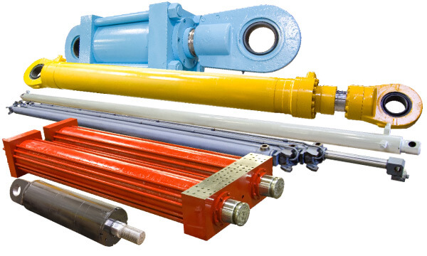
Can lift cylinders be used in hydraulic vehicle lifts?
Yes, lift cylinders are commonly used in hydraulic vehicle lifts. Here’s an explanation of their utilization in hydraulic vehicle lifts:
Hydraulic vehicle lifts are devices used to raise vehicles for maintenance, repairs, or storage purposes. Lift cylinders play a crucial role in the lifting operation of these hydraulic lifts.
In hydraulic vehicle lifts, lift cylinders are typically positioned vertically and connected to the lifting platform or arms. The lift cylinders work by converting hydraulic pressure into mechanical force, allowing the platform or arms to lift the vehicle. When the hydraulic system is activated, the hydraulic fluid is pressurized, and it flows into the lift cylinders. The force exerted by the pressurized fluid causes the lift cylinders to extend, resulting in the upward movement of the lifting platform or arms.
Lift cylinders used in hydraulic vehicle lifts are usually hydraulic cylinders. Hydraulic systems offer the advantages of smooth operation, precise control, and high lifting capacities. The hydraulic system includes a pump, control valves, hydraulic lines, and the lift cylinders. By controlling the flow of hydraulic fluid to the lift cylinders, operators can easily adjust the lifting height and position of the vehicle.
One of the key benefits of using lift cylinders in hydraulic vehicle lifts is their ability to provide stable and controlled lifting. The lift cylinders are designed to handle the weight of vehicles and ensure safe and secure lifting. They offer reliable support and stability throughout the lifting process, allowing technicians to work on vehicles with confidence.
In addition to lifting capabilities, lift cylinders in hydraulic vehicle lifts may incorporate safety features such as locking mechanisms or overload protection. These safety measures enhance the overall performance and reliability of the lifts, ensuring the safety of both the vehicle and the operators.
Overall, lift cylinders are integral components in hydraulic vehicle lifts, enabling the vertical lifting motion and providing stability during vehicle maintenance and repair operations. Their hydraulic operation, strength, and safety features make them essential for efficient and safe vehicle lifting.
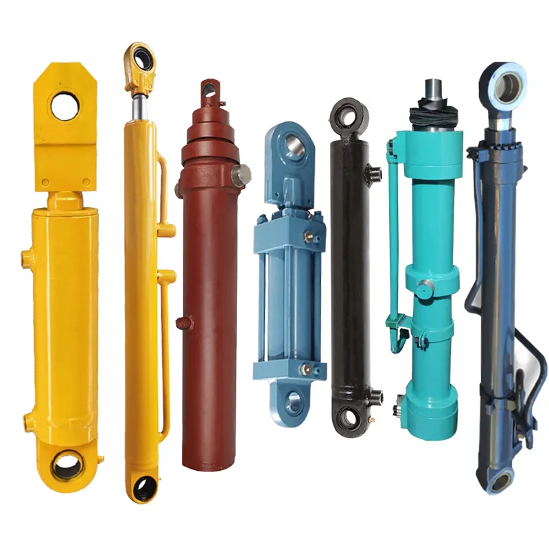
How Does a Lift Cylinder Contribute to Load Leveling and Distribution?
A lift cylinder plays a significant role in load leveling and distribution, ensuring stability and balanced weight distribution in various applications. Here’s a detailed explanation of how a lift cylinder contributes to load leveling and distribution:
- Vertical Force Generation:
- Multi-Cylinder Systems:
- Self-Leveling Mechanisms:
- Force Sensing and Control:
- Structural Support and Stability:
- Customization for Specific Applications:
When a lift cylinder is activated, it generates a vertical force that lifts or supports a load. The force exerted by the cylinder is directly proportional to its hydraulic or pneumatic pressure and the effective area of the piston. By adjusting the pressure or controlling the flow of fluid or gas into the cylinder, the force can be precisely regulated to achieve load leveling and distribution.
In applications where load leveling and distribution are critical, multiple lift cylinders may be used in a system. These cylinders work in synchronization to evenly distribute the load and maintain balance. By connecting the cylinders in parallel or series, the hydraulic or pneumatic pressure can be distributed across all cylinders, ensuring that each cylinder contributes proportionately to the load leveling and distribution process.
Some lift cylinder systems incorporate self-leveling mechanisms to automatically adjust the position and angle of the load. These mechanisms utilize sensors or feedback systems that monitor the load distribution and make real-time adjustments to the lift cylinders. If an imbalance or uneven weight distribution is detected, the self-leveling mechanisms activate the appropriate lift cylinders to counteract the imbalance and restore equilibrium. This contributes to load leveling and distribution, preventing excessive stress on specific areas or components.
Advanced lift cylinder systems may employ force sensing and control technologies to achieve precise load leveling and distribution. Force sensors are integrated into the lifting mechanism, allowing real-time monitoring of the forces exerted by the cylinders. This information is then used to adjust the hydraulic or pneumatic pressure, ensuring that each cylinder contributes optimally to the load distribution. By continuously monitoring and controlling the forces, the lift cylinder system can adapt to changing load conditions and maintain stable load leveling and distribution.
Lift cylinders provide structural support and stability to the load-bearing components in various applications. By evenly distributing the load, the cylinders help prevent excessive stress or strain on specific components. They ensure that the weight is evenly spread across the supporting structure, reducing the risk of structural damage or failure. Lift cylinders also contribute to the overall stability of the system, minimizing unwanted movements or vibrations caused by imbalanced loads.
Lift cylinders can be customized and tailored to specific applications to optimize load leveling and distribution. Factors such as cylinder size, stroke length, bore diameter, and material strength can be selected based on the load characteristics and weight distribution requirements of the particular application. By considering the specific needs of the application, lift cylinders can be designed and implemented to achieve the desired load leveling and distribution performance.
Overall, a lift cylinder is a crucial component in achieving load leveling and distribution in various applications. Whether through vertical force generation, multi-cylinder systems, self-leveling mechanisms, force sensing and control, structural support, or customization, lift cylinders contribute to maintaining stability, balance, and even weight distribution, ensuring optimal performance and safety in diverse industrial and mechanical systems.
What are the safety considerations when using lift cylinders?
When using lift cylinders, it is crucial to prioritize safety to prevent accidents and ensure the well-being of operators and bystanders. Here are some important safety considerations when using lift cylinders:
1. Proper Training:
Operators should receive proper training on the safe operation of lift cylinders. They should be familiar with the equipment’s capabilities, limitations, and recommended operating procedures. Training should include understanding hydraulic systems, load capacities, stability factors, and proper positioning techniques.
2. Inspection and Maintenance:
Routine inspection and maintenance of lift cylinders are essential for identifying any potential safety hazards. Regularly check for leaks, damaged components, loose connections, or signs of hydraulic fluid contamination. Ensure that all safety features, such as pressure relief valves and load holding devices, are functioning correctly.
3. Load Capacity and Stability:
It is crucial to know and adhere to the lift cylinder’s load capacity limits specified by the manufacturer. Overloading the cylinder can lead to equipment failure, instability, or uncontrolled movements. Properly distribute the load to maintain stability and prevent tipping or imbalance.
4. Secure Mounting:
Ensure that the lift cylinder is securely mounted to the equipment or structure. Follow the manufacturer’s guidelines for proper attachment methods and torque specifications. Loose or improper mounting can compromise the stability and safety of the lifting operation.
5. Control of Movement:
Exercise caution and maintain control over the movement of the lift cylinder. Avoid sudden or jerky motions that can destabilize the load or cause the equipment to tip. Use smooth and controlled movements, and be aware of any potential obstacles or hazards in the surrounding area.
6. Personal Protective Equipment (PPE):
Operators and personnel involved in the lifting operation should wear appropriate personal protective equipment, such as safety glasses, gloves, and steel-toed shoes. PPE helps protect against potential hazards, including hydraulic fluid leaks, falling objects, or accidental contact with moving parts.
7. Emergency Procedures:
Establish clear emergency procedures in case of equipment malfunction, hydraulic system failure, or any other unforeseen circumstances. Operators should be trained on how to respond to emergencies, including proper shutdown procedures, communication protocols, and evacuation plans.
8. Environmental Factors:
Consider the environmental conditions in which the lift cylinders are being used. Factors such as extreme temperatures, high humidity, or corrosive atmospheres can affect the cylinder’s performance and safety. Take appropriate measures, such as using protective covers or selecting cylinders with suitable material coatings, to mitigate these risks.
In summary, ensuring safety when using lift cylinders involves proper training, regular inspection and maintenance, adhering to load capacity limits, secure mounting, controlled movement, using personal protective equipment, establishing emergency procedures, and considering environmental factors. By following these safety considerations, the risk of accidents or injuries associated with lift cylinder operations can be minimized.


editor by CX 2023-11-01