
Product Description
FC Type telescopic cylinder for dump truck and trailer body
1. Company Information
Found 1995,w are 1 of the biggest hydraulic cylinder manufacturer in China, specialized in design, R & D and manufacturing of hydraulic machinery products etc, with its annual production capaciy of 2 square meters.There are 700 sets of mnufacturing equipment .
Product Description
2. hydraulic telescopic cylinder for dump truck drawing and parameter
FC type
| ITEM | MODEL NO. | # of Stages | Largest Moving Stage Diameter(mm) | stroke(mm) | the largest sleeve OD(mm) | mounting distance(mm) |
| 1 | WTHY FC-3-110-3205 | 3 | 110 | 3205 | 168 | 343 |
| 2 | WTHY FC-3-110-3460 | 3 | 110 | 3460 | 168 | 343 |
| 3 | WTHY FC-3-129-2980 | 3 | 129 | 2980 | 218 | 343 |
| 4 | WTHY FC-3-129-3205 | 3 | 129 | 3205 | 218 | 343 |
| 5 | WTHY FC-3-129-3460 | 3 | 129 | 3460 | 218 | 343 |
| 6 | WTHY FC-3-129-3880 | 3 | 129 | 3880 | 218 | 343 |
| 7 | WTHY FC-3-129-4270 | 3 | 129 | 4270 | 218 | 343 |
| 8 | WTHY FC-4-129-4280 | 4 | 129 | 4280 | 218 | 343 |
| 9 | WTHY FC-4-129-4280 | 4 | 129 | 4280 | 218 | 343 |
| 10 | WTHY FC-4-129-5180 | 4 | 129 | 5180 | 218 | 343 |
| 11 | WTHY FC-3-149-4270 | 3 | 149 | 4270 | 244 | 343 |
| 12 | WTHY FC-4-149-3680 | 4 | 149 | 3680 | 218 | 343 |
| 13 | WTHY FC-4-149-3980 | 4 | 149 | 3980 | 218 | 343 |
| 14 | WTHY FC-4-149-4280 | 4 | 149 | 4280 | 244 | 343 |
| 15 | WTHY FC-4-149-4620 | 4 | 149 | 4620 | 244 | 343 |
| 16 | WTHY FC-4-149-4940 | 4 | 149 | 4940 | 244 | 343 |
| 17 | WTHY FC-4-149-5180 | 4 | 149 | 5180 | 244 | 343 |
| 18 | WTHY FC-4-149-5460 | 4 | 149 | 5460 | 244 | 343 |
| 19 | WTHY FC-4-169-4280 | 4 | 169 | 4280 | 244 | 343 |
| 20 | WTHY FC-4-169-4620 | 4 | 169 | 4620 | 244 | 343 |
| 21 | WTHY FC-4-169-4940 | 4 | 169 | 4940 | 244 | 343 |
| 22 | WTHY FC-4-169-5180 | 4 | 169 | 5180 | 244 | 343 |
| 23 | WTHY FC-4-169-5460 | 4 | 169 | 5460 | 244 | 343 |
| 24 | WTHY FC-5-169-5355 | 5 | 169 | 5355 | 244 | 343 |
| 25 | WTHY FC-5-169-5780 | 5 | 169 | 5780 | 244 | 343 |
| 26 | WTHY FC-5-169-6180 | 5 | 169 | 6180 | 244 | 343 |
| 27 | WTHY FC-5-169-6830 | 5 | 169 | 6830 | 244 | 343 |
| 28 | WTHY FC-5-169-7130 | 5 | 169 | 7130 | 244 | 343 |
| 29 | WTHY FC-5-169-7630 | 5 | 169 | 7630 | 244 | 343 |
| 30 | WTHY FC-5-169-8130 | 5 | 169 | 8130 | 244 | 343 |
| 31 | WTHY FC-5-169-9030 | 5 | 169 | 9030 | 244 | 343 |
| 32 | WTHY FC-5-169-9530 | 5 | 169 | 9530 | 244 | 343 |
| 33 | WTHY FC-4-191-5460 | 4 | 191 | 5460 | 274 | 343 |
| 34 | WTHY FC-5-191-5780 | 5 | 191 | 5780 | 274 | 343 |
| 35 | WTHY FC-5-191-6180 | 5 | 191 | 6180 | 274 | 343 |
| 36 | WTHY FC-5-191-7130 | 5 | 191 | 7130 | 274 | 343 |
| 37 | WTHY FC-5-191-7630 | 5 | 191 | 7630 | 274 | 343 |
| 38 | WTHY FC-5-191-8130 | 5 | 191 | 8130 | 274 | 343 |
| 39 | WTHY FC-5-191-9030 | 5 | 191 | 9030 | 274 | 343 |
| 40 | WTHY FC-5-191-9530 | 5 | 191 | 9530 | 274 | 343 |
| 41 | WTHY FC-5-214-7610 | 5 | 214 | 7610 | 274 | 343 |
| 42 | WTHY FC-5-214-9030 | 5 | 214 | 9030 | 274 | 343 |
FE type
| ITEM | MODLE NO. | # of Stages | Largest Moving Stage Diameter(mm) | stroke(mm) | mounting distance(mm) |
| 1 | WTHY FE-3-110-3205 | 3 | 110 | 3205 | 1449 |
| 2 | WTHY FE-3-110-3460 | 3 | 110 | 3460 | 1609 |
| 3 | WTHY FE-3-129-3460 | 3 | 129 | 3460 | 1449 |
| 4 | WTHY FE-3-129-3880 | 3 | 129 | 3880 | 1609 |
| 5 | WTHY FE-3-149-2900 | 3 | 149 | 2900 | 1320 |
| 6 | WTHY FE-3-149-3200 | 3 | 149 | 3200 | 1420 |
| 7 | WTHY FE-3-149-3500 | 3 | 149 | 3500 | 1520 |
| 8 | WTHY FE-3-149-3880 | 3 | 149 | 3880 | 1644 |
| 9 | WTHY FE-4-149-4280 | 4 | 149 | 4280 | 1450 |
| 10 | WTHY FE-4-149-4940 | 4 | 149 | 4940 | 1529 |
| 11 | WTHY FE-4-149-4620 | 4 | 149 | 4620 | 1484 |
| 12 | WTHY FE-4-169-4280 | 4 | 169 | 4280 | 1394 |
| 13 | WTHY FE-4-169-4450 | 4 | 169 | 4450 | 1437 |
| 14 | WTHY FE-4-169-4620 | 4 | 169 | 4620 | 1479 |
| 15 | WTHY FE-4-169-4940 | 4 | 169 | 4940 | 1529 |
| 16 | WTHY FE-4-169-5000 | 4 | 169 | 5000 | 1574 |
| 17 | WTHY FE-4-169-5180 | 4 | 169 | 5180 | 1604 |
| 18 | WTHY FE-5-169-5355 | 5 | 169 | 5355 | 1394 |
| 19 | WTHY FE-5-169-5780 | 5 | 169 | 5780 | 1559 |
| 20 | WTHY FE-5-169-6180 | 5 | 169 | 6180 | 1527 |
| 21 | WTHY FE-5-169-6480 | 5 | 169 | 6480 | 1604 |
| 22 | WTHY FE-5-169-6830 | 5 | 169 | 6830 | 1674 |
| 23 | WTHY FE-5-169-7130 | 5 | 169 | 7130 | 1769 |
| 24 | WTHY FE-5-191-6180 | 5 | 191 | 6180 | 1527 |
| 25 | WTHY FE-5-191-9030 | 5 | 191 | 9030 | 2177 |
| 26 | WTHY FE-6-191-7420 | 6 | 191 | 7420 | 1677 |
| 27 | WTHY FE-5-214-6830 | 5 | 214 | 6830 | 1662 |
| 28 | WTHY FE-5-214-7130 | 5 | 214 | 7130 | 1722 |
3. hydraulic telescopic cylinder for dump truck produce line
700 sets manufacturing equipment,such as cold drawing production line ,heat treatment production line ,surface treatment production line,testing equipment,various digital-control machining equipment,gantry style linear electroplating production line.
4. hydraulic telescopic cylinder for dump truck quality guarantee system
Program before Delivery
1). Trial Operation Test
2). Start-up Pressure Test
3). Pressure-Tight Test
4). Leak Test
5). Full Stroke Test
6). Buffer Test
7). Testing the Effect of Limit
8). Load Efficiency Test
9). Reliability Test
Every piece of hydraulic cylinder are tested and will send out only after they are pasted the each test.
Our company has abundant technical force and perfect testing means. By making wide technical and business cooperation with many related enterprises, universities, colleges and institutes both at home and abroad, and employing senior engineers and software engineers, we have greatly strengthened and improved our designing, processing, and testing abilities.
5. After-service
1).Pre-sale service: Keep communicating with the truck manufacturers , including selection of product model , design of hydraulic system, test of performance and analysis of the accident. Once the problems occur, we will solve them immediately together with truck manufacturers .
2).The sale service: Provide training and technical support for users.
3).After-sale service: Solve the problem firstly, then analyse responsibility ; Replace the system components immediately if any need.
4). 24 hours telephone service hotline.
6.Exhibition and partner
7. FAQ
Q1:What’s the brand name of your products ?
A:Generally,we use our own brand “WTJX”,OEM is also available as required.
Q2:Hydraulic cylinder internal leakage?
A: There are 3 main reasons causing internal leakage :Overload,polishing is not well controlled,bad seal kits.As is known to all,vehicles in China are often overload,our products all designed to bear the overload power.We have numerical control machine to assure the polish processing .And we use the imported seals to meet customers’ demands.
Q3:Does your piston rod get ruptured easily?
A: Hard chrome plating quenched and tempered 45# steel for piston rod to assure sufficient hardness and toughness.
Q4:Is your design reasonable? What about your product safe coefficient?
A:We have R&D team with abundant design experience. We also established production, education, and research cooperation with universities . Rest assured.
Q5:What about the quality feedback of your products?
A: Guarantee the quality from the raw material. We have cold drawing production line and nickel-chrome electroplating production line , so we can produce cold-drawing pipe and hard-chrome pipe used for hydraulic cylinder. !!!
WE HAVE NEVER RECEIVED EVEN ONCE QUALITY COMPLAINT FOR MANY YEARS OF INTERNATIONAL TRADE.
Q6:Is the sample free?
A:Yes.In our acceptable range, we can offer a sample by charging freight. And we will return the fee after you place bulk order.
Q7:How about the delivery time?
A: Over 700 sets advanced equipments to meet customer’s large demand in short delivery time.Generally ,it’s 20 days.
Q8:What ‘s the after-service?
A:If the quality can’t meet your requirement ,we will pay all your lost and offer technical support to solve your problem!!!
/* March 10, 2571 17:59:20 */!function(){function s(e,r){var a,o={};try{e&&e.split(“,”).forEach(function(e,t){e&&(a=e.match(/(.*?):(.*)$/))&&1
| Material: | Steel |
|---|---|
| Usage: | Tipping Truck |
| Structure: | Telescopic Cylinder |
| Standard: | Standard |
| Pressure Direction: | Single-acting Cylinder |
| Rated Pressure: | 16-20MPa |
| Customization: |
Available
|
|
|---|
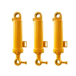
How does a lift cylinder contribute to smooth and controlled lifting motion?
A lift cylinder plays a crucial role in ensuring smooth and controlled lifting motion in various applications. Here’s an explanation of how a lift cylinder contributes to this:
1. Hydraulic Operation:
A lift cylinder typically operates using hydraulic power. Hydraulic systems utilize pressurized fluid to generate force and motion. The lift cylinder is connected to the hydraulic system, and when the hydraulic fluid is pressurized, it exerts force on the piston inside the cylinder. This force causes the cylinder to extend or retract, enabling the lifting motion. The hydraulic operation of the lift cylinder provides a smooth and consistent force, resulting in a controlled and precise lifting motion.
2. Synchronization:
In some applications, multiple lift cylinders are used together to achieve synchronized lifting. These cylinders work in tandem, ensuring that the lifting force is evenly distributed and that the load remains level throughout the lifting process. The synchronization of lift cylinders contributes to a smooth and balanced lifting motion, reducing the risk of tilting or instability.
3. Control Valves:
Lift cylinders are often equipped with control valves that allow operators to control the flow and pressure of the hydraulic fluid. By adjusting these control valves, operators can regulate the speed and force of the lifting motion. This provides precise control over the lifting process, allowing for smooth and controlled movements tailored to the specific requirements of the application.
4. Damping and Cushioning:
Some lift cylinders incorporate damping and cushioning mechanisms to further enhance the smoothness and control of the lifting motion. These mechanisms help absorb shocks and vibrations, preventing sudden jolts or jerky movements during the lifting process. Damping and cushioning features contribute to a more comfortable and controlled lifting experience, particularly when dealing with delicate or sensitive loads.
5. Load Capacities:
Lift cylinders are designed to handle specific load capacities based on their size, construction, and specifications. By selecting the appropriate lift cylinder for the intended load, operators can ensure that the lifting motion remains smooth and controlled. Overloading or underloading the lift cylinder can lead to instability or uneven lifting, affecting the overall smoothness and control of the motion.
In summary, a lift cylinder contributes to smooth and controlled lifting motion through its hydraulic operation, synchronization (if applicable), the use of control valves, damping and cushioning mechanisms, and appropriate load capacities. These factors work together to provide reliable and precise lifting, enhancing safety and efficiency in various applications.
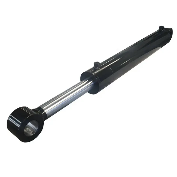
How does a lift cylinder contribute to load clamping and gripping?
A lift cylinder plays a significant role in load clamping and gripping applications by providing the necessary force and control to securely hold objects in place. Lift cylinders, also known as hydraulic cylinders, are widely used in various industrial settings for lifting, pushing, pulling, and holding heavy loads.
When it comes to load clamping and gripping, lift cylinders contribute in the following ways:
- Clamping Force: Lift cylinders can generate a high clamping force, which is utilized to tightly hold objects together. By exerting pressure on clamping mechanisms or jaws, the cylinders ensure a secure grip on the load, preventing undesired movement or slippage.
- Gripping Action: Lift cylinders are integrated into gripping devices or gripper systems to perform gripping actions. These cylinders provide the force necessary to close the gripper fingers or jaws around the object, creating a firm grip. The gripping action allows for safe transportation, manipulation, or assembly of the load.
- Controlled Pressure: Lift cylinders offer precise control over the clamping or gripping force. The hydraulic system controlling the cylinders allows for adjustable pressure settings, enabling operators to tailor the clamping force according to the specific requirements of the application. This control ensures optimal grip without damaging the load.
- Positioning and Alignment: Lift cylinders assist in the positioning and alignment of the load during clamping or gripping operations. They can be used to finely adjust the position of the clamping or gripping elements, ensuring accurate and proper alignment with the load. This precision helps achieve a secure and balanced grip on the object.
The use of lift cylinders in load clamping and gripping applications offers several advantages. They provide reliable and powerful clamping or gripping force, enabling safe and efficient handling of objects. The adjustable pressure and precise control allow for customization based on the load characteristics, ensuring optimal grip without causing damage.
In summary, lift cylinders contribute significantly to load clamping and gripping by providing the necessary force, control, and adjustability. Their integration into clamping mechanisms and gripper systems enhances safety, accuracy, and productivity in various industrial processes.
What is a lift cylinder and how does it function in hydraulic systems?
A lift cylinder, also known as a hydraulic lift cylinder or hydraulic lifting cylinder, is a device used in hydraulic systems to generate linear motion and provide lifting force. It is a type of hydraulic actuator that converts hydraulic pressure into mechanical force to lift heavy loads. Here’s an explanation of what a lift cylinder is and how it functions in hydraulic systems:
A lift cylinder consists of a cylindrical barrel, a piston, and a rod. The barrel is a hollow tube that houses the piston and allows fluid to flow in and out. The piston is a cylindrical component that separates the barrel into two chambers. The rod, attached to the piston, extends from the cylinder to connect with the load or the mechanism being lifted.
The lift cylinder operates based on the principles of Pascal’s law, which states that pressure exerted on a fluid in a confined space is transmitted equally in all directions. Here’s how a lift cylinder functions:
1. Extension:
When pressurized hydraulic fluid enters one side of the cylinder (the chamber behind the piston), it applies force on the piston, causing it to move in the direction of the load. This movement extends the rod outward, lifting or pushing the load.
2. Retraction:
Conversely, when the hydraulic fluid is supplied to the other side of the cylinder (the chamber in front of the piston), the pressure differential causes the piston to move in the opposite direction. This retracts the rod, lowering or pulling the load.
3. Control Valve:
The flow of hydraulic fluid into and out of the lift cylinder is controlled by a directional control valve. The valve regulates the direction and amount of fluid entering the cylinder, determining whether the cylinder extends or retracts. This control allows for precise and controlled lifting and lowering of the load.
4. Force and Load Capacity:
The force generated by the lift cylinder is determined by the hydraulic pressure applied to the piston and the effective area of the piston. By increasing or decreasing the hydraulic pressure, the lifting force can be adjusted to meet the specific load requirements.
5. Application:
Lift cylinders are widely used in various hydraulic systems, including hydraulic lifts, cranes, forklifts, dump trucks, and construction equipment. They provide the necessary force to lift heavy objects, perform material handling tasks, and support heavy loads in a controlled and efficient manner.
In summary, a lift cylinder is a hydraulic actuator that converts hydraulic pressure into mechanical force for lifting heavy loads. It functions by utilizing hydraulic fluid pressure to move the piston and extend or retract the rod, enabling the lifting or lowering of the load. The control valve regulates the fluid flow, and the force generated by the lift cylinder is determined by the hydraulic pressure and piston area. Lift cylinders find extensive applications in hydraulic systems across various industries.


editor by CX 2024-02-05